News & Blog
How Do You Wire a 4V110-06 Solenoid Valve for Safe Operation?
A packaging-line maintenance team has a failed 4V110-06 valve, a new coil on the bench, and a production window that closes in forty minutes. The pressure is on, but the risk is not the valve body—it is the wiring. One wrong terminal, a missing fuse, or a coil rated for the wrong voltage can turn a simple replacement into a burned PLC output, a tripped line, or an unsafe restart. That is why buyers and technicians ask: How Do You Wire a 4V110-06 Solenoid Valve for Safe Operation? The practical answer begins with verification, not speed: confirm the coil voltage on the nameplate, identify the DIN connector or terminal arrangement, isolate the power, use correct cable glands and strain relief, add fusing and surge suppression, and test the circuit before the valve is returned to service. Raydafon Technology Group Co.,Limited supports this process with clearly identified coil options, stable terminal hardware, and product documentation that helps procurement teams match the valve to the control circuit. Safety also depends on the environment: washdown areas need sealed enclosures, vibrating machines need locked terminals, and DC circuits need flyback protection to protect sensitive outputs. The goal is not merely to make the valve click; it is to create a repeatable wiring method that keeps maintenance quick, spare parts compatible, and operators protected. This guide walks through the decisions in the order a technician should make them, from reading the label to the first safe power-up, with tables and checklists that purchasing and maintenance teams can reuse.
Map the Valve, Coil, and Power Supply Before You Strip a Wire
Pain scene: a purchasing team orders a replacement 4V110-06 Solenoid Valve for a line that runs on 24 VDC, but the spare coil in the storeroom is marked for AC service. The technician sees the same connector shape, installs the coil, and only after power-up does the coil overheat or the control fuse trip. The cost is not just a coil; it is downtime, rework, and doubt about every spare in the cabinet.
Solution: treat the nameplate and datasheet as the first wiring tool. Record the coil voltage, AC or DC service, rated current or power, duty cycle, connector type, and any protective earth requirement. Confirm the power supply and control output can deliver the coil inrush and holding current. Check whether the circuit needs a separate relay, a fused output, or a suppression module. Raydafon Technology Group Co.,Limited helps procurement teams reduce this risk by matching coil options to the order code and by providing clear identification on the product and documentation.
| Checkpoint | Why It Matters | Acceptable Evidence |
|---|---|---|
| Coil voltage | Prevents immediate coil burnout or weak actuation | Nameplate, datasheet, and measured supply voltage |
| AC or DC service | Determines polarity, suppression method, and test procedure | Coil marking and order code confirmation |
| Connector style | Prevents forced fit, loose terminals, and wrong gasket use | DIN connector or terminal box photo compared with datasheet |
| Circuit protection | Limits damage if the coil or cable fails | Fuse rating, breaker curve, and PLC output rating |
For a 4V110-06 Solenoid Valve, this mapping step is also a procurement control. When the order code, coil label, and panel drawing agree, the maintenance team can wire with confidence instead of guessing from connector shape alone.
Match the 4V110-06 Coil Voltage to the Control Circuit
Pain scene: a machine is rebuilt with a new control panel, and the original AC coil is connected to a DC output through an interface relay. The valve chatters, the relay contacts pit, and the operator reports inconsistent shifting. The wiring looks neat, but the electrical match is wrong.
Solution: verify the actual coil voltage under load, not only at the power supply terminals. Use a meter at the coil connector while the circuit is energized by a qualified person, and compare it with the coil rating. For DC coils, confirm polarity and use a flyback diode or an approved suppression module. For AC coils, confirm line and neutral arrangement, use the correct RC or MOV protection where specified, and keep the coil circuit separate from signal cables. Label the cable at both ends with the valve tag, voltage, and function.
| Parameter | What to Check | Safe Practice |
|---|---|---|
| Rated coil voltage | 24 VDC, 110 VAC, 220 VAC, or another code | Match exactly to the supply and order code |
| Voltage tolerance | Supply sag during machine cycle | Measure at the coil; avoid using an unloaded reading |
| Coil current | Inrush and holding current | Confirm relay, fuse, and wire gauge are adequate |
| Duty cycle | Continuous or intermittent service | Use a coil rated for the actual operating cycle |
Raydafon Technology Group Co.,Limited can support buyers who need to confirm coil options before a spare parts order is released, helping avoid the common mismatch between a 4V110-06 Solenoid Valve and the panel supply.
Terminate the DIN Connector Without Loose Strands or Reverse Polarity
Pain scene: a maintenance technician replaces a coil during a short shutdown window. The screw terminals are tightened, but one fine strand bridges to the adjacent terminal. The valve works during the test, then fails intermittently after the machine starts vibrating. The root cause is not the valve; it is the termination.
Solution: isolate power, remove the connector, and inspect the gasket, terminal block, and strain relief. Strip the cable to the correct length, use the specified crimp ferrules where required, and keep strands inside the terminal. For DC coils, confirm positive and negative before tightening. For AC coils, confirm line and neutral. Connect protective earth where the product and local codes require it. Tighten the cable gland so the cord cannot be pulled, then refit the connector with a clean gasket.
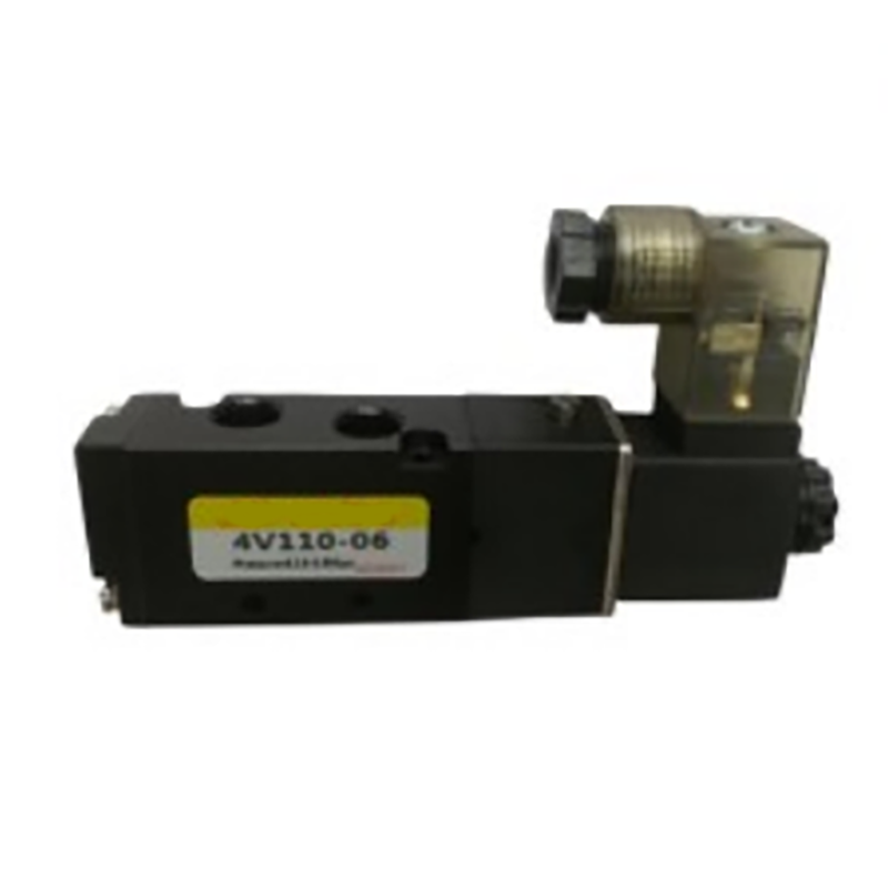
| Terminal / Feature | Typical Function | Inspection Point |
|---|---|---|
| Coil terminal 1 | DC positive or AC line, depending on design | Verify against datasheet; do not assume from position alone |
| Coil terminal 2 | DC negative or AC neutral, depending on design | Confirm polarity for DC; confirm neutral for AC |
| Protective earth | Safety bonding where required | Check continuity to the enclosure and machine frame |
| Gasket and gland | Seal and strain relief | No cuts, no cable pull, no moisture path |
When buying a 4V110-06 Solenoid Valve from Raydafon Technology Group Co.,Limited, request the connector and coil details with the quotation so the panel team can prepare the correct cable and suppression parts before the valve arrives.
Add Surge Suppression and Fusing to Protect the Coil and PLC Output
Pain scene: a DC solenoid valve is wired directly to a PLC output module. When the valve de-energizes, the collapsing coil field produces a voltage spike. The PLC output fails weeks later, and the replacement module fails again because the cause was never addressed.
Solution: treat the coil as an inductive load that needs a defined shutdown path. For DC circuits, a flyback diode across the coil is common, with the cathode connected to the positive side according to the circuit design. For AC circuits, use an RC network or MOV selected for the coil voltage and expected transients. Add a fuse or breaker sized for the coil and cable. Keep coil cables away from analog signals and encoder wiring. Use terminal blocks and labels that make the suppression device visible during troubleshooting.
| Protection Device | Best For | Placement | Benefit |
|---|---|---|---|
| Flyback diode | DC solenoid coils | Across the coil terminals, observing polarity | Clamps reverse voltage and protects output devices |
| RC network | AC solenoid coils | Across the coil or at the connector | Reduces switching transients and contact arcing |
| MOV | AC or DC transient limiting | At the coil circuit or panel entry | Absorbs short-duration overvoltage events |
| Fuse or breaker | Coil and cable protection | Upstream of the coil circuit | Limits damage from short circuits |
Raydafon Technology Group Co.,Limited understands that buyers of the 4V110-06 Solenoid Valve often need more than a valve body; they need a coil and connector combination that fits the panel protection scheme and keeps spare parts predictable.
Test, Seal, and Label the Wiring for Reliable Daily Operation
Pain scene: a food-processing line uses washdown cleaning, and a solenoid valve is mounted near a drain. The valve works after installation, but water enters the connector and causes corrosion. In another area, vibration loosens a terminal screw and creates an intermittent fault that is hard to find.
Solution: complete a structured test before handover. With power isolated, check continuity of each conductor, confirm no short between coil terminals and earth, inspect the gasket, and verify strain relief. With power restored under qualified supervision, confirm coil voltage, valve response, and absence of abnormal heat or noise. Seal unused openings, route cables with a drip loop, and label the valve tag, voltage, and control function. Add the wiring date and technician initials to the maintenance record.
| Test | Tool | Pass Criterion |
|---|---|---|
| Continuity | Multimeter | Correct conductor end-to-end; no cross-terminal bridge |
| Insulation to earth | Insulation tester where permitted | No leakage path through cable damage or moisture |
| Coil voltage under load | Multimeter | Within coil rating and supply tolerance |
| Functional response | Machine control test | Valve shifts cleanly; no chatter or abnormal heat |
For procurement teams, this test list becomes a receiving and installation checklist. A 4V110-06 Solenoid Valve from Raydafon Technology Group Co.,Limited can be specified with the connector and coil data needed to support that checklist from the first order.
Q&A Group 1: Voltage, Polarity, and Connector Pinout
Question: How Do You Wire a 4V110-06 Solenoid Valve for Safe Operation when the coil voltage and connector pinout are not clearly marked?
Answer: Stop before connecting power. Use the order code, nameplate, and datasheet to confirm whether the coil is AC or DC and what voltage it requires. Inspect the connector for terminal numbers or markings, and compare them with the valve documentation. For DC coils, confirm which terminal is positive and which is negative; for AC coils, confirm line and neutral. If the marking is missing or damaged, contact the supplier with photos of the coil, connector, and nameplate before wiring. Never use trial-and-error power-up on an unknown coil.
| Unknown Item | Risk | Safe Action |
|---|---|---|
| Coil voltage | Burnout or weak actuation | Read nameplate and datasheet; measure supply |
| AC or DC service | Wrong suppression and polarity | Confirm coil marking before connection |
| Terminal function | Reverse polarity or short circuit | Use documented pinout; ask Raydafon for confirmation |
Q&A Group 2: Fusing and First Power-Up
Question: What is the safest first power-up procedure after wiring a 4V110-06 Solenoid Valve?
Answer: First complete all dead tests: continuity, visual inspection, terminal tightness, gasket condition, and insulation check where appropriate. Confirm that the fuse or breaker rating matches the coil and cable. Then, under qualified supervision, energize the circuit briefly and check coil voltage at the connector, valve response, and any abnormal heat, noise, or smell. If a PLC output is used, verify that the suppression device is installed and that the output module is rated for the coil load. Record the result and label the circuit before returning the machine to normal production.
| First Power-Up Step | Check | Stop Condition |
|---|---|---|
| Pre-power inspection | Terminals, gasket, strain relief, labels | Loose strand, missing earth, damaged seal |
| Protection check | Fuse, breaker, suppression device | Wrong rating or missing suppression |
| Brief energization | Coil voltage and valve response | Chatter, overheating, fuse trip, unusual noise |
Raydafon Support and Contact
Raydafon Technology Group Co.,Limited supplies reliable pneumatic and solenoid valve solutions for procurement teams, machine builders, and maintenance departments that need clear specifications, stable quality, and practical support. From confirming the correct coil voltage for a 4V110-06 Solenoid Valve to preparing connector and spare-parts details before shipment, Raydafon Technology Group Co.,Limited helps customers reduce wiring mistakes and keep production lines running. Send your valve nameplate photo, panel voltage, and connector requirement for a fast review, or visit https://www.raydafon-couplings.com and contact [email protected] to discuss your next order.
Research References
Smith, R. A., and Patel, M. 2018. Electromagnetic Compatibility of Solenoid Valve Drive Circuits in Industrial Control Panels. IEEE Transactions on Industry Applications, 54(6).
Chen, L., and Wang, H. 2020. Surge Suppression Methods for DC Solenoid Coils in Pneumatic Systems. Journal of Electromagnetic Engineering and Science, 20(3).
Kumar, S., and Lee, J. 2019. Reliability Assessment of DIN Valve Connectors under Vibration and Thermal Cycling. IEEE Transactions on Components, Packaging and Manufacturing Technology, 9(10).
Garcia, P., and Rossi, F. 2021. Safety-Oriented Wiring Verification for Pneumatic Solenoid Valves. Journal of Loss Prevention in the Process Industries, 72.
Thompson, D., and Zhao, Y. 2017. Flyback Diode Selection for Solenoid Coil Protection in PLC Outputs. IET Power Electronics, 10(12).
Nakamura, K., and Sato, T. 2022. Insulation Resistance and Dielectric Testing of Industrial Solenoid Coils. IEEE Transactions on Dielectrics and Electrical Insulation, 29(2).
Brown, A., and Miller, C. 2016. IP Enclosure Practice for Washdown Solenoid Valve Installations. Journal of Food Process Engineering, 39(5).
Ali, M., and Hassan, N. 2023. Fault Diagnosis of 5/2 Solenoid Valves Using Electrical Signatures. Measurement, 207.
Wilson, J., and Taylor, S. 2015. Procurement Specifications for Solenoid Valve Coils in Automated Assembly Lines. International Journal of Production Research, 53(14).
Wang, Q., and Kim, S. 2024. Transient Voltage Effects on AC Solenoid Valve Coils and Protective RC Networks. Electric Power Systems Research, 226.
Related News
- What are the advantages of an inverted telescopic design in a 2100 PSI hydraulic cylinder?
- What should I look for when buying a truck trailer ladder for sale?
- What is the difference between a split bush and a solid bush?
- What is the maximum horsepower rating for a PTO speed reducer gearbox?
- How much land can a horse drawn plough till in a day?
- What is the maximum weight you can load on dumbbell discs?
Leave me a message
New Products
News Recommendations